Early flying designs and machines
I enjoy building stuff from plans.


Codex Atlanticus
Da Vinci sketched many partial drawings of wings and fuselages - but did not leave a single complete set of plans for a flying machine. There is disagreement about whether he ever built a model or actual machine based on his drawings.
Back in 1961 Robert Coyle published plans reconstructing a flying machine based on the drawings in the Codex Atlanticus and the Codex on the Flight of Birds. The plans were published in a museum series kit by Incunabula and Petri Dish Publications. Robert's work remains a stunning attempt to breath life into Da Vinci's sketches.
I started the build in 2006, but put it aside when we started to research a super-tribunal for the ACT. I finished it four years later in 2010, a year after the ACT Civil and Administrative Tribunal came into operation. I have been tossing around the possibility of building a full sized version out of light mountain Ash - and this weekend started the long haul of collecting the wood necessary for the framework.
The wings themselves are made out of 22 wood struts each with exactly the same graceful bend. Each strut is made out of a number of pieces of local timber glued together to give the right shape. Once the glue sets and the pieces are assembled, the entire structure has incredible strength for almost no weight. The wings are hinged half way along - ropes along the leading edge allow the pilot to vary the shape of the wing tip.


The fuselage envisages a person strapped to a board, moving the wings and pedaling. Leather straps hold a tail to the fuselage and wings for stability. The wings are covered in mesh rather than silk.


And the final form, wall mounted.
It will take a little while to complete the full size version :) A good project for over winter - with the first frosts hitting here in the Australian high country tonight.

The drawing is in the Codex Atlanticus. I knew that this would not be a pretty creature to build - even Da Vinci only bothered to draw one of the wings. So before I committed to the build, I tried a simple version - just to see how it might work in action.

To my surprise - the motion was amazing and so I set about constructing a full size version out of local wood.


Until almost the very final stage of building the wings, I was at a loss to visualize how it would look in final form.
Here it is in final form at the Bungendore Show.
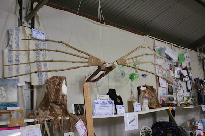
One of the more ugly bits of work I have engaged in. The wings work like the fingers of a hand... the only way it would fly is by pulling itself through the air :) Perhaps something for Qantas to consider as part of its cost cutting.


Some of the earliest aircraft or designs also used this type of approach to give stability in extremely low speed situations. Some of Da Vinci's wings also used this approach. In the case of designs and actual aircraft, instead of flaps, wings or part of a wing were warped through ropes and pulleys - sometimes with mixed results.
One of the more successful European designs was the Etrich Taube (Dove) which was produced in large numbers before the first world war in Germany and Austria.
I first bumped into the Taube when studying trademark law - it is a classic case of how a designer can loose control of intellectual property. But it is also an example of what can happen to a market when it is freed from the constraints of paying unproductive licence fees.

I loved this design from the first moment I first saw it. In 2012 I put aside a couple of weeks to build a replica from local timber.


I didn't want to hide the construction detain behind a silk cover - so covered it with a light mesh instead.


The final form hangs in my study, gently turning in the breeze :) Look closely, and you will find a repurposed teaspoon, a factor overlooked in the germinal study of teaspoon disappearance.


The first Australian designed aircraft flew on 16 July 1910, 16 years after the first flight by the Australian inventor Lawrence Hargraves on 12 November 1894.
In turn, both Duigan, a Victorian farmer, and Hargraves were familiar with the flight properties of hunting and returning boomerangs of the first people.
I have been collecting plans and related material to attempt a scale reconstruction.
The image is based on the Lewis replica donated to the Victorian Museum.

I should note that my friend Chris Sutton has pointed to the efforts of the New Zealand inventor Richard Pearse who may have been the first person to fly a powered heavier than air aircraft.
Duigan prepared some sets of plans for the Biplane 'Pusher' (a pusher locates the propeller at the rear of the plane, spinning in a different direction to a conventional pull propellor setup). He also prepared a set for a prototype. The prototype (the plan give imperial dimensions) and final version (which does not) are similar. There are a some differences, based on flight experience, the main variance being the omission of a second back elevator, streamlined rudder and more complex stressed back frame assembly, in favor of a simplified arrangement. The wheel arrangement in the final version also different. Some photographs were taken of the plane/s at different stages.


A couple of full-size reconstructions have been attempted, and some historical model reconstructions have been prepared for display in Victorian museums.
Nevertheless, there are still difficulties with any rebuilding. Firstly, there is some doubt about the actual wing length and the final length of the airplane, and some questions about the actual dimensions. Secondly, photographs of the flight show some features not included in the plans, and the plans themselves include some elements not found in the photo. Finally, some of the more sophisticated detail, such as the multi-component spar construction, will be obscured by wing covering.
Faced with these challenges, any reconstruction must make a couple of best guesses at different points. I have also chosen to build for flight, and this has prompted a couple of other slight departures.
The next question is one about size of the model. A matter for individual choice, i plan to eventually hang this on a ceiling, so am comfortable with a relatively large model. In this case, i have chosen a 1:12 scale, allowing the direct translation of 1' to 1" (and a final model size of 24 by 30 inches).
1. Plans
The first plan shows the layout of the wing and other covered elements on a 1" grid.
The length of the main wings is the subject of some doubt. Having tried a couple of alternatives, and compared to the photographs, i have elected to use the prototype length of 24'. Note that the width is only partly represented on the plan (the midpoint of the wings is marked in red). I have staggered the rib arrangement at the extremities.
The wing 'extantions' are not given measurements in the original plans, and i have estimated them to be 3'6" in length with the upper pair being 1'6" across and the lower 1'. Because these could not materially add to lift, and forward speed was too low for a great contribution to glide, Duigan may have reworked these between tests, and they may have been shorter than might appear from other reconstructions.
The position of ribs in the rudder is guesswork, based on the need to keep the element rigid to resist collapse.
2. Wings and elevators
The curve of the spars lends themselves to being cut sequentially on the same piece of wood. Unfortunately, there are three slightly different spar forms, which is curious, given the added lift had the main wing spar length of 3'6" been made standard throughout and the advantages of a single size. Instead 26 of the 3'6" spars, 7 of the 3' spars and 7 of the 2'6" spars will need to be cut. As these will not be visible, I have elected to cut them from sheet ply to add to structural integrity.
In other situations, these might be manufactured using a 3D printer to replicate the multiple wood and curves of the original (a similar approach was taken in the museum model of the Flyer by Hasegawa, where the spars were constructed in polystyrene).

Two same-size wing frames, the front elevator, and the back elevator are constructed. I have used a slow think superglue gel and a kicker to weld the wood into position. I tried a number of approaches - settling for a strongly reinforced wing structure (above).
Each frame is then covered by cloth or tissue and coated with dope to seal and tighten the covering. I practiced with a couple of different covers before opting for tissue. A set of test doped linen wings (below) gave a nice but inconsistent coverage (i may eventually use the linen elements for a backlight model where i want the final look to be translucent).

The sealant stage cannot be skipped or foreshortened. Four coats of dope for tissue and wood sealant for cloth are applied allowing each coat to dry for about 12 hours. Between the first two coats, fine misting water is applied to add to the tightening process. Each coat results in a tighter covering and greater translucency.
Side frames are then constructed.

The main elements are then assembled (below is the tissue variant, which is being made to fly, at wind tunnel point). After testing in a makeshift wind tunnel, i recast the wings slightly wider than the plans would indicate, to reduce turbidity and increase lift. Those involved in flying a full scale replica noted that the design has problems with excessive air resistance. I also opted to use > scale spars and structural elements to assist rigidity in flight.

I have given the canvass surfaces two coats of a matt acrylic coat (Buff on top, Deck Wood below) and all wood a dark wood stain. This high contrast treatment unifies the structure and the slight difference in canvass colour slightly compensates for underwing shadows. Doped linen can have a significant yellow cast but I have opted not to try to replicate that.

Spars, undercarriage configuration and engine block placement/balancing varied from flight to flight. I tried a couple of different configurations and wheels before settling for a mixed metal/wood combination.


Back in 1961 Robert Coyle published plans reconstructing a flying machine based on the drawings in the Codex Atlanticus and the Codex on the Flight of Birds. The plans were published in a museum series kit by Incunabula and Petri Dish Publications. Robert's work remains a stunning attempt to breath life into Da Vinci's sketches.
I started the build in 2006, but put it aside when we started to research a super-tribunal for the ACT. I finished it four years later in 2010, a year after the ACT Civil and Administrative Tribunal came into operation. I have been tossing around the possibility of building a full sized version out of light mountain Ash - and this weekend started the long haul of collecting the wood necessary for the framework.
The wings themselves are made out of 22 wood struts each with exactly the same graceful bend. Each strut is made out of a number of pieces of local timber glued together to give the right shape. Once the glue sets and the pieces are assembled, the entire structure has incredible strength for almost no weight. The wings are hinged half way along - ropes along the leading edge allow the pilot to vary the shape of the wing tip.


The fuselage envisages a person strapped to a board, moving the wings and pedaling. Leather straps hold a tail to the fuselage and wings for stability. The wings are covered in mesh rather than silk.


And the final form, wall mounted.
It will take a little while to complete the full size version :) A good project for over winter - with the first frosts hitting here in the Australian high country tonight.
Da Vinci - articulated wing
Years ago, I stumbled across a sketch by Da Vinci of an articulated wing - where the power provided through a simple circular motion such as turning a pedal was converted into a complex motion - akin to flapping a wing.
The drawing is in the Codex Atlanticus. I knew that this would not be a pretty creature to build - even Da Vinci only bothered to draw one of the wings. So before I committed to the build, I tried a simple version - just to see how it might work in action.

To my surprise - the motion was amazing and so I set about constructing a full size version out of local wood.


Until almost the very final stage of building the wings, I was at a loss to visualize how it would look in final form.
Here it is in final form at the Bungendore Show.

One of the more ugly bits of work I have engaged in. The wings work like the fingers of a hand... the only way it would fly is by pulling itself through the air :) Perhaps something for Qantas to consider as part of its cost cutting.

Da Vinci - Helicopter

Etrich Taube
Most aircraft built and flown use flaps (ailerons) to turn, rise and drop. This is not always the case - some modern designs are being tested by CERN and NASA of aircraft with wing surfaces that morph to give the craft better control in high speed situations.Some of the earliest aircraft or designs also used this type of approach to give stability in extremely low speed situations. Some of Da Vinci's wings also used this approach. In the case of designs and actual aircraft, instead of flaps, wings or part of a wing were warped through ropes and pulleys - sometimes with mixed results.
One of the more successful European designs was the Etrich Taube (Dove) which was produced in large numbers before the first world war in Germany and Austria.
I first bumped into the Taube when studying trademark law - it is a classic case of how a designer can loose control of intellectual property. But it is also an example of what can happen to a market when it is freed from the constraints of paying unproductive licence fees.

I loved this design from the first moment I first saw it. In 2012 I put aside a couple of weeks to build a replica from local timber.


I didn't want to hide the construction detain behind a silk cover - so covered it with a light mesh instead.


Etrich Taube - 2 seater - Cockpit and engine
The final form hangs in my study, gently turning in the breeze :) Look closely, and you will find a repurposed teaspoon, a factor overlooked in the germinal study of teaspoon disappearance.


Rebuilding the Duigan Biplane

The first Australian designed aircraft flew on 16 July 1910, 16 years after the first flight by the Australian inventor Lawrence Hargraves on 12 November 1894.
In turn, both Duigan, a Victorian farmer, and Hargraves were familiar with the flight properties of hunting and returning boomerangs of the first people.
I have been collecting plans and related material to attempt a scale reconstruction.
The image is based on the Lewis replica donated to the Victorian Museum.

I should note that my friend Chris Sutton has pointed to the efforts of the New Zealand inventor Richard Pearse who may have been the first person to fly a powered heavier than air aircraft.
Duigan prepared some sets of plans for the Biplane 'Pusher' (a pusher locates the propeller at the rear of the plane, spinning in a different direction to a conventional pull propellor setup). He also prepared a set for a prototype. The prototype (the plan give imperial dimensions) and final version (which does not) are similar. There are a some differences, based on flight experience, the main variance being the omission of a second back elevator, streamlined rudder and more complex stressed back frame assembly, in favor of a simplified arrangement. The wheel arrangement in the final version also different. Some photographs were taken of the plane/s at different stages.


A couple of full-size reconstructions have been attempted, and some historical model reconstructions have been prepared for display in Victorian museums.
Nevertheless, there are still difficulties with any rebuilding. Firstly, there is some doubt about the actual wing length and the final length of the airplane, and some questions about the actual dimensions. Secondly, photographs of the flight show some features not included in the plans, and the plans themselves include some elements not found in the photo. Finally, some of the more sophisticated detail, such as the multi-component spar construction, will be obscured by wing covering.
Faced with these challenges, any reconstruction must make a couple of best guesses at different points. I have also chosen to build for flight, and this has prompted a couple of other slight departures.
The next question is one about size of the model. A matter for individual choice, i plan to eventually hang this on a ceiling, so am comfortable with a relatively large model. In this case, i have chosen a 1:12 scale, allowing the direct translation of 1' to 1" (and a final model size of 24 by 30 inches).
1. Plans
The first plan shows the layout of the wing and other covered elements on a 1" grid.
The length of the main wings is the subject of some doubt. Having tried a couple of alternatives, and compared to the photographs, i have elected to use the prototype length of 24'. Note that the width is only partly represented on the plan (the midpoint of the wings is marked in red). I have staggered the rib arrangement at the extremities.
The wing 'extantions' are not given measurements in the original plans, and i have estimated them to be 3'6" in length with the upper pair being 1'6" across and the lower 1'. Because these could not materially add to lift, and forward speed was too low for a great contribution to glide, Duigan may have reworked these between tests, and they may have been shorter than might appear from other reconstructions.
The position of ribs in the rudder is guesswork, based on the need to keep the element rigid to resist collapse.
2. Wings and elevators
The curve of the spars lends themselves to being cut sequentially on the same piece of wood. Unfortunately, there are three slightly different spar forms, which is curious, given the added lift had the main wing spar length of 3'6" been made standard throughout and the advantages of a single size. Instead 26 of the 3'6" spars, 7 of the 3' spars and 7 of the 2'6" spars will need to be cut. As these will not be visible, I have elected to cut them from sheet ply to add to structural integrity.
In other situations, these might be manufactured using a 3D printer to replicate the multiple wood and curves of the original (a similar approach was taken in the museum model of the Flyer by Hasegawa, where the spars were constructed in polystyrene).

Two same-size wing frames, the front elevator, and the back elevator are constructed. I have used a slow think superglue gel and a kicker to weld the wood into position. I tried a number of approaches - settling for a strongly reinforced wing structure (above).
Each frame is then covered by cloth or tissue and coated with dope to seal and tighten the covering. I practiced with a couple of different covers before opting for tissue. A set of test doped linen wings (below) gave a nice but inconsistent coverage (i may eventually use the linen elements for a backlight model where i want the final look to be translucent).

The sealant stage cannot be skipped or foreshortened. Four coats of dope for tissue and wood sealant for cloth are applied allowing each coat to dry for about 12 hours. Between the first two coats, fine misting water is applied to add to the tightening process. Each coat results in a tighter covering and greater translucency.
Side frames are then constructed.

The main elements are then assembled (below is the tissue variant, which is being made to fly, at wind tunnel point). After testing in a makeshift wind tunnel, i recast the wings slightly wider than the plans would indicate, to reduce turbidity and increase lift. Those involved in flying a full scale replica noted that the design has problems with excessive air resistance. I also opted to use > scale spars and structural elements to assist rigidity in flight.

I have given the canvass surfaces two coats of a matt acrylic coat (Buff on top, Deck Wood below) and all wood a dark wood stain. This high contrast treatment unifies the structure and the slight difference in canvass colour slightly compensates for underwing shadows. Doped linen can have a significant yellow cast but I have opted not to try to replicate that.

Spars, undercarriage configuration and engine block placement/balancing varied from flight to flight. I tried a couple of different configurations and wheels before settling for a mixed metal/wood combination.


Comments
paper airplane designs for distance and speed | how to make a boomerang airplane | how to make a paper airplane eagle | best paper airplane design for distance and accuracy | paper airplane that flies far and straight | dihedral vs anhedral | science behind paper airplanes | classic dart paper airplane | zazoom internet | nakamura paper airplane